Quantcast
Channel: AutomobileHeat » electronics
Viewing all 1695 articles
Browse latest View live

Magufuli Atikisa Mitandao Ya Kijamii Nchi Kenya…….Wakenya Wammwagia Sifa Kibao, Watamani Awe Rais Wao

$
0
0

Uchapakazi wa Rais Dkt John Magufuli unatuma ujumbe si kwa maafisa wa Tanzania pekee, bali na nchi za jirani pia na kuwaacha viongozi wa nchi hizo kwenye wakati mgumu.   Kenya ambayo imekuwa ikifuatilia siasa za Tanzania tangu wakati wa kampeni, imeonesha kupenda mbinu za Magufuli na wananchi wake wanatamani mtu kama yeye.   Kwa kipindi kifupi alichoingia madarakani, Magufuli amefanya mambo makubwa na wananchi wamependa.   Ziara yake ya kushtukiza kwenye hospitali ya Muhimbili ilifichua uovu mwingi na kupelekea kufutwa kwa bodi ya wakurugenzi wa hospitali hiyo na kumuondoa Kaimu Mkurugenzi wake, Dk Hussein Kidanto.   Ili kupunguza matumizi makubwa ya fedha za serikali kwaajili ya kugharamia safari za nje za viongozi wa nchi, Magufuli aliamua kuzisitisha mara moja.   Dkt Magufuli pia alielekeza kiasi cha shilingi milioni 225 zilichangwa kwaajili ya kugharamia hafla ya wabunge kupongezana mjini Dodoma zipelekwe kwenda kununua vitanda. Badala yake shilingi milioni 15 pekee zilitumika kwaajili ya sherehe hiyo.    Siku chache baadaye vitanda hivyo na vifaa vingine vilinunuliwa na kupelekwa Muhimbili.   Jumatatu hii Magufuli alitangaza kuondoa sherehe za maadhimisho ya siku ya Uhuru December 9 na fedha za maandalizi hayo zitumike kwa mambo mengine muhimu.   Hayo na mambo mengine yamefanya Dkt Magufuli atrend nchini Kenya.   Hizi ni baadhi ya tweets za wakenya:

[via LEKULE]

Follow us @automobileheat – lists / @sectorheat


Benki ya Standard Chartered yateua Mkurugenzi wa kwanza Mtanzania

$
0
0

Sanjay Rughani (pichani) anakuwa Mtanzania wa kwanza kuiongoza benki ya Standard Chartered Tanzania akipokea uongozi wa benki hiyo kutoka kwa aliyekuwa mkurugenzi wake, Liz Lloyd, ambaye amerudi katika makao makuu ya benki hiyo, London, kuchukua nafasi ya Mshauri wa Kisheria wa benki hiyo. Sanjay alijiunga na benki ya Standard Chartered Tanzania mwaka wa 1999 akiwa kama Meneja msaidizi wa kitengo cha Fedha. Baada ya miaka miwili Sanjay alipata cheo cha Meneja wa kitengo cha Fedha kwa Bara la Afrika, kazi ambayo aliifanya akiwa katika makao makuu ya benki hiyo, London. Alirudi nyumbani Tanzania mwaka wa 2002 na kupata cheo cha Mkuu wa Kitengo cha Fedha nchini Tanzania, kazi ambayo aliifanya hadi mwaka wa 2006.  Mwaka wa 2007, Sanjay alipata tena cheo kingine, wakati huu akihamishiwa Ghana, ambapo aliongoza Kitengo cha Fedha nchini humo huku pia akisimamia Afrika Magharibi, yaani Gambia, Cote d’ Ivoire na Sierra Leone,  kazi ambayo aliifanya hadi Mei, 2013. Juni, 2013  Sanjay alipandishwa tena cheo na kuwa Mkuu wa Operesheni za Kifedha na Mratibu wa Huduma za Kifedha kwa Bara la Afrika akiongoza kitengo hicho ambacho ni sehemu ya Kitengo Kikuu cha Fedha katika nchi kumi na tano za Afrika, akilenga kuboresha huduma za kifedha za benki hiyo zilingane na huduma zake za kimataifa katika nchi zilizoendelea. Sanjay alifanya kazi hii hadi alipoteuliwa kuwa Mkurugenzi wa Benki hiyo hapa Tanzania hapo mwanzoni wa mwezi huu wa kumi na moja. Lamin Manjang, Mkurugenzi wa benki ya Standard Chartered Kenya na Afrika Mashariki , amesema, “ Nafurahi kumkaribisha tena Sanjay nyumbani Tanzania na kwenye timu yangu ya Afrika Mashariki kufutatia umahiri wake katika kazi mbalimbali ambazo amezifanya katika benki yetu. Pia nafurahi kuwa sasa benki yetu nchini Tanzania ina Mkurugenzi wake wa kwanza wa Kitanzania. Hii inaonyesha ubora wa wafanyakazi wetu nchini Tanzania. Tunaendelea kuweka kipaumbele kwa kuwapa wafanyakazi wetu bora nyadhifa mbalimbali za uongozi barani Afrika ili kuweza kuboresha maendeleo katika nchi mbalimbali ambapo tunafanya shughuli zetu za kibenki.”  Tanzania inaendelea kupewa kipaumbele katika mipango ya benki hiyo katika bara la Afrika na Afrika Mashariki haswa kutokana na ukuaji wake wa kiuchumi na kuweko katika ‘Klabu ya 7%’, ambayo ni listi ya nchi ambazo uchumi wake unakadiriwa kuendelea kukua kwa kasi zaidi katika miaka kumi ijayo. Kufuatia kuteuliwa kwake Mkurugenzi huyo mpya wa benki ya Standard Chartered Tanzania, Sanjay Rughani alisema , “Tanzania ina fursa nyingi sana za kibiashara na ninafurahi kurudi nyumbani kuiongoza benki ya Standard Chartered kwenda kwenye hatua nyingine ya kimaendeleo. Nchi yetu inaendelea kuchangia mafanikio ya Umoja wa Afrika Mashariki kwa njia mbalimbali ikiwemo ukuaji mzuri wa uchumi. Pia ugunduzi wa hifadhi za gesi nchini Tanzania unatarajiwa kuleta maendeleo zaidi ya kiuchuni hapa nchini kwetu.” Sanjay ana shahada ya udhamili ya Kifedha na Rasilimali watu, na shahada ya Uchumi. Pia ni mwanachama wa Chama cha Wahasibu, ACCA. Sanjay pia ni Mjumbe wa Bodi wa benki ya Standard Chartered Uganda. Ameoa na ana watoto wawili.

[via LEKULE]

Follow us @automobileheat – lists / @sectorheat

What is Transfer Function?

$
0
0

Introduction In Analyzing and designing of any system, the most important factor is the mathematical modeling of that system. There are many mathematical models to describe control systems. In physics, transfer function maybe defined as mathematical representation (in terms of frequency) of interrelation between input and output in linear time uninterrupted systems with zero pint equilibrium and zero initial conditions. If talking particularly about control systems then it can be defined as the ratio of the Laplace transform of the output variable to the Laplace transform of the input variable, with all zero initial conditions. Transfer function is function of complex variables. The transfer function can be obtained by simple algebraic jugglery of differential equations that illustrates the system. Transfer function can represent higher order systems also, even infinite dimensionless systems which regulates on partial differential equations. Transfer Function The input-output explanation of system is elementally the spreadsheet of all possible input-output pairs. Like for linear system, spreadsheet can be described by single input single output pair. For example the impulse response or the step response. Transfer Function of a Linear System Consider the linear input-output system, the differential equation (1) that express it will be: Where, u is the input and y is the output the differential equation is completely described by two polynomials: The characteristic polynomial of system is polynomial a(s). Taking u (t) = e st as input to find transfer function so the output will also be an exponential function that will be y (t) = y 0 e st . Inserting signals in equation (1), we get: If a , it will give, The transfer function of this linear system thus will be rational function, Note that, a(s) and b(s) are given above as polynomial of system. Transfer Function of Exponential Signals In linear systems, exponential signals plays vital role as they come into sight in solving differential equation (1). It also comes in picture when we see impulse response of a linear system. Exponentials or sum of exponentials can signify many signals. A constant signal is e αt with =0. We can show this signal in explicit form as: As mentioned above, combination of exponentials can represent many signals as it’s a combination of cosine as well as sine function so let’s examine a linear system which is answering back to the exponential input signal u(t) = e st we consider the state space system: Think the input signal as u (t) = e st , suppose that where is the ith eigenvalue of A. The state is as follows: The integral can be solved since The result of the above equation can now be written as: This is a linear combination of exponential functions with exponents e st and In which are eigenvalues of A. Only one term of the output is proportional to the input that is: u (t) = e st . This is the pure exponential response when the initial state is: x (0) = (sI-A) -1 B Both state and output are proportional to input and output only has exponential response. The ratio of output and input is the transfer function of the system and is written as: The response of a system to an exponential input can be written as: Conclusion As we move towards the end of this control tutorial we have a now almost a complete insight of all the entities in a control system. In this article we have discussed transfer function which is input-output explanation of system. We studied transfer function of linear systems. In the next tutorial that will be the last one we will study poles and zeros of a control system and the major differences between them. I hope you will stay tuned to us as this will be the last article of this chain.

[via LEKULE]

Follow us @automobileheat – lists / @sectorheat

Introduction to Laplace Transform

$
0
0

Definition Laplace transformation converts differential and integral equations into rather simple algebraic equations. Laplace transform is nothing but a simple operational tool, used to solve linear differential equations with constant coefficients. The transformation is only applied to general signals and not to sinusoidal signals. Also, it cannot handle steady state conditions. It enables us to study complicated control systems with integrators, differentiators and gains. On basis of Laplace transformation we analyze LCCODE’s and circuits with several sources, inductors, resistors and capacitors. For a given function f (t) such that t 0, its Laplace transformation is written as F(s) = L f (t) and is written as: From the above equation we conclude that the transformation converges when the limit exists and diverge when it does not. The L notation recognizes that integration always proceeds over t = 0 to t=1 and that the integral involves an integrator dt instead of the usual dt. Laplace transformation method Laplace transformation reduces the problem of solving a differential equation to an algebraic problem. Laplace theory is based on Lerch’s cancellation law which is given as follows: In a differential equation, y(t) is an unknown variable depending on time. Laplace Integral The Laplace integral of a function g (t) is given as: The integral formulae are derived by illustrating g (t) = 1, g (t) = t and g (t) = t² By summarizing we get: Some important transformation rules: Following are some properties of general calculus that can be implemented on the transformation: The sum of two integrals can be combined: Lerch’s cancellation law is applied on Laplace transformation: Integration by parts or sometimes called the t-derivative rule: Constant can be written out of the integral: Laplace Transforms of Periodic Functions At times the non-homogenous term in a linear differential equation is a periodic function. Any function f (t) can be said a t-periodic function if we write it as f (t+T) = f (t) like the period of sine and cosine is radians where period of tangent is For a t-period the function is written as: Provided that t 0 Now the Laplace transform is given as: Example 1: Using the definition we have: For improper integral to converge we need s > a. Here: Example 2: Let’s have a look at Laplace transform of Sin at and Cos at. Using the Euler’s formula we can write: By Laplace transform we have: By comparing real and imaginary parts we get: Conclusion Though the topic of Laplace transform is much wider, we have tried to enclose the basics of it in this article. What is the basic idea and concept of Laplace transform and how it works. We discussed a couple of examples to elaborate it more. As we move on to the end of these tutorials we will study the most important part in the upcoming one that is Transfer Function. It is the factor on which a control systems depends so stay tuned to us for the tutorial.

[via LEKULE]

Follow us @automobileheat – lists / @sectorheat

Introduction to First-Order Systems

$
0
0

Introduction There are two methods to analyze functioning of a control system that are time domain analysis and control domain analysis. In time domain analysis the response of a system is a function of time. It analyzes the working of a dynamic control system. This analysis can only be applied when nature of input plus mathematical model of the control system is known. It is not easy to express the actual input signals by simple equations as the input signals of the control systems are not fully known. There are two components of any system’s time response, transient response and steady response. Typical and standard test signals are used to judge the behavior of typical test signals. The characteristics of an input signal are constant acceleration, constant velocity, a sudden change or a sudden shock. We discussed four types of test signals that are Impulse Step, Ramp, Parabolic and another important signal is sinusoidal signal. In this article we will be discussing first order systems. First order system The system whose input-output equation is a first order differential equation is called first order system. The order of the differential equation is the highest degree of derivative present in an equation. First order system contains only one energy storing element. Usually a capacitor or combination of two capacitors is used for this purpose. These cannot be connected to any external energy storage element. Most of the practical models are first order systems. If a system with higher order has a dominant first order mode it can be considered as a first order system. Response of a first order system It is not much difficult to find the response of a first order system as the degree of differential equation is one. There are two important points on which this analysis is actually based: The time constant for a first order system is given by : t=RC (for a system with resistors and capacitors) t=L/R (for a circuit with inductors). The response of a first order system is given by: Provided that, input is constant and t> 0, where v (0) is voltage or current at t=0. Now we will see the unit responses with respect to first order systems and will see the transfer functions accordingly. 1. Unit Impulse in First Order System As we know the unit impulse input is: r(t) = δ(t), t ≥0 For Laplace transform the Transfer function of input: R(s) =1. The output transform will be: By taking inverse Laplace transform: Y(t)= e-t/T/T, t ³ 0 The impulse input generates transfer function as the output. 2. Unit Step Response of First Order System The Transfer function of input is: R(s)=1/s Therefore the unit step response is: Expanding in Partial fraction: Take the inverse Laplace transform: y (t) = 1 – e-t/T, t ³ 0. 3. Unit Ramp Response of First Order System The input, r (t) = t for t ³ 0. In Laplace transform, The transfer function of input: R(s)=1/s² The output transform is: Expanding in Partial fraction: Taking the inverse Laplace transform: y (t) = t – T + Te-t/T, t ³ 0. Conclusion In this tutorial we have enlightened first order systems and their response. We calculated time constant and time response of these systems. We discussed both time response and ramp response of the first order systems. The upcoming tutorial will discuss the same aspects of second order systems so stay tuned. We have much more to study and share with you in the upcoming articles.

[via LEKULE]

Follow us @automobileheat – lists / @sectorheat

Contactors and Electric Control Panels

$
0
0

There is often the situation when an operator needs to turn on or off a piece of machinery which presents a high load on the electrical circuit. Some examples could include big pool pumps, industrial lathe machines or heavy hangar automatic doors. To switch on such high currents is not an easy task and this is where contactors come into play. These are high current Normally Open relays with protection against arcs and designed for specific applications. Contactors can have many poles in order to control many loads from the same switch or to control 3 phase circuits. Like any relay the contactor will have a coil that when energized will close the circuit shunting the contacts. Depending on contactor the energizing voltage will differ and can be DC or AC. It is important to note that most contactors don’t offer over-current protection. The ones that incorporate such protection are usually referred to as motor starters. Figure 1 shows a schematic of a circuit used to switch on a motor. The elements incorporated in the dash and dot rectangle are part of the motor starter. The left side of the diagram represents the control circuit which in this case operates at 24V ac. Whenever the B button is pushed, contactor C is closed, M motor starts and indicator light turns on. As mentioned there are many types of contactors, each intended for a specific operation. Improper selection of the right contactor is the most common cause of its failure. Besides selecting the proper current rating you need to know what kind of equipment you will be controlling. An inductive motor behaves very differently during transient period than an incandescent lamp even if they have the same power rating. You can use the table below, or the IEC 947-1 standard to help you select the proper contactor for your application. Conclusion In conclusion whenever you will have to switch on and off heavy loads you will need to use contactors. They are also often found in automation systems, offering the possibility to safety control a piece of machinery from remote locations or from devices that normally could not carry such high current.

[via LEKULE]

Follow us @automobileheat – lists / @sectorheat

Tips to Optimize the Life of Electrical Switchgear

$
0
0

Introduction Modern manufacturing processes, as well as computer processes, primarily seek to reduce on equipment downtime. Equipment failure accounts for millions in damage and lost revenue. A number of such detrimental scenarios can be eliminated, or reduced through optimizing the switchgear life and enhancing reliability. With limited finances available for new equipment purchase and capital projects, the only workable solution is maintenance of the existing equipment. Do note that switchgear is composed of bus structures, as well as more active components that include fused switching devices and circuit breakers. The article focuses more on low and medium voltage circuit gears, as they are in wide application in switchgear and switchboards. The following tips do come in handy. Maintenance The primary switchgear maintenance procedures include cleaning, inspection, tightening, lubrication and exercising. The maintenance schedule depends on equipment condition, operating environment and criticality to the whole system. Various contaminants such as dust, used lubricants and dirt deteriorate the conductive materials, insulation and protective installations. The engineer or technician on site should prepare a detailed maintenance plan for each lineup. Reconditioning In-shop reconditioning is a more intensive maintenance activity. It involves testing the circuit breakers against ANSI standards, disassembly, cleaning and refurbishing. The reconditioned circuit breaker is again tested as per the standards before re-attachment. Do note that reconditioning is necessary if the in-house maintenance plans does not sort out the circuit breakers within the industry standards. Record and Trend Maintenance In some cases, the maintenance testing fails to track the performance of the circuit breakers, resulting in unnoticed degradation of the parts. Do note that switchgear components can still function even when without design tolerance. However, for enhanced reliability and extended life, tracking test data is necessary to have a better notion of the system expected longevity. The engineer should come up with a predictive performance plan that primarily focuses on engineering analysis of the testing data. Performance of the switchgear versus expected lifetime Equipment Upgrade Keep up with technological developments through replacing aging switchgear with new line-ups, even with regular maintenance. Do note that advances in material science and controls mean better performing circuit breakers, on-board diagnostics and reduced maintenance requirements. Taking advantage of the developments only means a timely upgrade and replacement. When considering an upgrade, the factors to consider including the operating environment, reliability, cost and availability of spare parts. However, the managers and engineers should also consider the capital cost, and any disruption to regular work process flow since interruptions without a feasible temporary re-route can be quite expensive in terms of production loss. Predictive Maintenance Luckily, for engineers and technicians, the advancements in switchgear equipment and reliability come hand in hand with the development of predictive maintenance tools. The integrated tools provide real-time monitoring, and impending failure warnings. In essence, they provide a valuable tool for predicting equipment life, maintenance requirements and recognizing conditions surpassed or un-noticed during the inspections. The common predictive maintenance tools include wireless temperature alarms, partial discharge monitoring tools, assessment tools, infrared inspections, and electronic trip units. Conclusion There are two extremes when it comes to switchgear performance; satisfactory performance and complete failure. The latter occurs as the equipment nears the end of the expected life. Lack of maintenance and inspection accelerates the period to non-function, or significantly reduces the expected equipment life. However, by implementing the highlighted tips, you can maximize the reliability and life of the components.

[via LEKULE]

Follow us @automobileheat – lists / @sectorheat

Typical Test Signals in Time Domain Analysis

$
0
0

Introduction Let’s recall the functioning of time domain analysis: When response of a dynamic system is expressed as a function of time it is called time domain analysis. This analysis can only be applied when nature of input plus mathematical model of the control system is known. It is not easy to express the actual input signals by simple equations as the input signals of the control systems are not fully known. There are two components of any system’s time response, transient response and steady response. Transient Response The element of the system that vanishes with time is called Transient response. It is the response of the system from rest or equilibrium to steady state. It is denoted by ctr (t) Steady-State Response The element of system response is achieved when the time approaches to infinity. The response of the system after transient response is basically called steady state response. It is denoted by css (t) Typical test signals in time domain The dynamic behavior of a system is manipulated and judged under the application and working of standard and typical test signals. The characteristics of an input signal are constant acceleration, constant velocity, a sudden change or a sudden shock. There are four types of typical test signals: Impulse Step, Ramp, Parabolic and another important signal is sinusoidal signal. Impulse Signal Impulse response in control system imitates sudden shock quality of actual input signal. Impulse is the output of system when given by small input. Impulse response emphasis on change in the system in reaction to some external change. It is the reply of the system to the direct delta input. When A=1 then the impulse signal is called Unit impulse signal. Step Signal The step signal defines the sudden change in properties of actual signal. It is being used to see the transient response of system as it gives you the idea about how the system reply to interruption and somehow the system stability. When A=1, the step is called unit step signal. Ramp Signal The ramp signal tells you the constant velocity attribute of actual input signal. It is being used to determine the behaviour of system with the velocity factor. When A=1, ramp signal is called unit ramp signal. Parabolic Signal Parabolic signal gives the constant acceleration distinction of actual input signal. It gives the idea about how the system will respond along with acceleration. When A=1, the parabolic signal is called unit parabolic signal. Conclusion The typical test signals judge the performance and working of a control system in the time domain analysis. We discussed the four times of signals that are Impulse step, ramp, parabolic and sinusoidal. These all have different graphs and different effects. These typical signals determine the behaviour and nature of a dynamic system.  

[via LEKULE]

Follow us @automobileheat – lists / @sectorheat


Time Domain Analysis of Control Systems

$
0
0

Introduction In our earlier articles we discussed about control systems. The system, in which, we arrange and combine constituents in such a way that our desired output is obtained. Also, the system is controlled so that the stability of system in not disturbed in any span of time. It depends upon two factors: Desired output Stability We analyze the features and functioning of every measurement system to know the working of system. There are two types of analysis in control systems: Time Domain Analysis Frequency Domain Analysis Time Domain Analysis In this article we will concentrate on time domain analysis. Time domain gives the view that how the state of dynamic system changes with respect to time when specific input is given. It gives you the manner of signal over time characteristics of a measuring signal. Models which we have consist of differential equations so some integration is being done to determine time response. For simple linear system, analysis is being done easily by analytical solutions. However, for nonlinear systems or those which have complicated inputs, their integration is carried out numerically or by using MATLAB. In time domain analysis, the time response of a linear dynamic system to an input is denoted as time’s function c (t) . We can calculate the time response if the input and model of system is known. The time response of linear system is the addition of transient response which depend on preliminary conditions and the steady-state response which is based on input of system. Transient Response The element of the system that vanishes with time is called Transient response. It is the response of the system from rest or equilibrium to steady state. It is denoted by (t) . Steady-State Response It is the element of system response that is achieved when the time approaches to infinity. The response of the system after transient response is basically called steady state response. It is denoted by (t) . Transient response doesn’t depend upon input of systems therefore can be analyzed using step input. Steady state depends upon input and dynamics of system and can be determined using different test signals by final value theorem. The equation of time response will be: Stability in Time Domain Analysis Stability in control system is said to be achieved if the output ultimately comes back to the state of equilibrium, when system is processed to an initial state. There are two terminologies in stability: Crucially Stable : In this case, the oscillation of output of system continues without end. Unstable : In this case, the output of system increases to a particular point. Steady State Error It indicates that the error between desired and actual output. It shows that at steady state the output is not corresponding with the input. Conclusion We have two ways to analyze working of any control system that are time domain analysis and frequency domain analysis. Both are two different principles to study functioning of any system. In this article we thoroughly discussed time domain analysis of control systems. How it works, Transient and steady-state response and the stability in time domain. The next tutorial will focus on Typical Test Signals in Time Domain Analysis. The next part of tutorials will be more informative for you so stay connected.

[via LEKULE]

Follow us @automobileheat – lists / @sectorheat

Difference Between Open Loop & Closed Loop Systems

$
0
0

Check the second part of Nasir’s tutorial on Control systems! Control systems are used to arrange and manage components in a way that the required condition or output is obtained. The word ‘control’ itself shows the command over any system. It is controlled when the systems is stable. There are two attributes of control system: Stability Desired output A control system can be functioned electrically, mechanically, pressure by fluid (gas or liquid), or it can be combination of these ways. In the preceding tutorial we introduced control systems, their principle of working, the variables involved in the functioning of control systems and the basic types. In this tutorial we will be conferring over the major types of control systems namely: Open loop systems and closed loop systems. The tutorial will deal with the chief differences between the two types. Let’s have a look on the basic working of the two systems: Open loop control systems An open-loop control system takes input under the consideration and doesn’t react on the feedback to obtain the output. This is why it is also called a non-feedback control system. There are no disturbances or variations in this system and works on fix conditions. Closed loop control systems A closed loop system is also referred as a feedback control system. These systems record the output instead of input and modify it according to the need. It generates preferred condition of the output as compared to the original one. It doesn’t encounter any external or internal disturbances. Differences between Open-loop and Closed-loop control systems These two types of control system have contrast with each other. They have dissimilarities some of which are discussed below: Effect of output – An open loop control system acts completely on the basis of input and the output has no effect on the control action. – A closed loop control system considers the current output and alters it to the desired condition. The control action in these systems is based on the output. Reaction to Internal and External Disturbances – An open loop control system works on fixed operation conditions and there are no disturbances. – A closed loop control system doesn’t encounter and react on external disturbances or internal variations. Stability – Open loop control systems are mostly stable. – In closed loop control systems stability is a major issue. Effect on gain – There is no effect on gain. – There is no-linear change in system gain. Implementation – The structure of open loop control system is rather easy to construct. These systems can be easily implemented. – The working principle and structures of closed loop control systems are rather complex and they are often difficult to implement. Cost – As an open loop control system is easy to implement, it needs lesser number of components to be constructed. Such systems need good calibration and lesser power rating. The overall cost of these systems is low. – As the principle is complex, a closed loop control system needs larger number of components than an open loop control systems. These systems comparatively need less calibration and higher power rating. The overall cost of these systems is higher. Examples – Stepper motors are one of the major examples of open-loop control systems. Automatic washing machine is yet another good example. – Television remote is the most significant example of closed loop control systems. A computer mouse is another good example. Conclusion The two types of control systems, open loop and control loop are entirely different from each other. Open loop is simple and works on the input while closed loop is complex and works on the output and modifies it. In the upcoming tutorial we will study time domain analysis of control systems in detail. So stay tuned to have more insight about the control structures.

[via LEKULE]

Follow us @automobileheat – lists / @sectorheat

Introduction to Control Systems

$
0
0

Control system is a way of arranging and combining components in such a way that the desired output is obtained. In other words, a system is said to be “controlled”, if it’s working in a stable mode without getting unstable in any span of time. From the above definition, one can say that a controlled system must have two attributes, which are: Stability Desired output A control system can be functioned electrically, mechanically, pressure by fluid (gas or liquid), or it can be combination of these ways. But it more preferred to operate this system by electrical means especially when computer is involved, even though interfusion are common these days. Variables Involved in a Control System In designing a control system, two types of variables are normally involved. These variables are used in control system to achieve the required position. 1. Controlled Variable It is the value or prerequisite that is determined and controlled. These variables are independent variables and are usually not influenced by external factors. These variables are controlled by the engineer, designing the control system, and those values are chose for these variables at which the system gives the best output. 2. Manipulated Variable The value or prerequisite that keep on changing as the controlled variables are changed. These variables are dependent variables and usually dependent on controlled variables. Let’s take a simple example of a fan dimmer. As someone changes the dimmer position i.e. changes the voltage, rpm of fan also decreases. In this example, voltage is the controlled variable while rpm of fan is the manipulated variable. Types of Control Systems There are three basic types of control systems that are feed forward control systems, feedback or closed loop control systems and the third type is open loop control systems. Let’s have a look on the functionalities of these different control systems. 1. Feed Forward Control System Feed forward is a type of system which counters the changes in its surroundings. It is used to maintain the wanted status of the system. The biggest advantage of this system is that it doesn’t permit the huge disturbance in the output. A system working on feed-forward behavior reacts to a calculated disturbance in a pre-defined way which is in contrast with a feedback system. It is used in automotive as engine torque demands, in servo systems (robotics) etc. 2. Feedback or Closed Loop Control System A feedback control system is also known as closed loop control system. In these systems out is recorded and alternations are made on the basis of feedback. It can generate the desired output condition compared to the original one. It is insensitive to external disturbances. It useful as the output of system can be measured with ease. 3. Open Loop Control System An open-loop control system is also referred as a non-feedback control system. These systems may not require a mathematical model of the physical system. It takes input under the consideration and doesn’t react on the feedback to determine the state of output. It doesn’t encounter any disturbance within the system or recompense them. Stepper motors are one of the major examples of open-loop control systems. Automatic washing machine is yet another good example. Conclusion Control systems today have various uses. In industry these systems are used to control the production or working of other machines. Different types of control systems work on different purposes. Control systems manage the behavior and working of a machine. The usefulness of control systems is in the precision and reliability of functions and equipment they can deliver. The field of control systems has its roots in industry and home appliances as well. In this tutorial I have just introduced the control systems, its basic types and their working. In the next article I will be analyzing open loop and closed loop control systems in more detail and will study what differentiates the two. 

[via LEKULE]

Follow us @automobileheat – lists / @sectorheat

Rais Magufuli atinga ofisini kwa waziri mkuu Majaliwa kwa mazungumzo.

$
0
0

Rais John Pombe Magufuli leo ametinga ofisini kwa waziri mkuu, Majaliwa Kassim Majaliwa na kufanya mazungumzo ya takribani saa moja. Rais aliingia ofisini kwa waziri mkuu Majaliwa majira ya saa tisa na kulakiwa na mwenyeji wake na baadae walikaa kwa mazungumzo yao wawili tu.   Baada ya mazungumzo hayo rais alizungumza kwa muda mfupi sana na makatibu muhutasi wa waziri mkuu kabla ya kuondoka kuelekea Ikulu.

[via LEKULE]

Follow us @automobileheat – lists / @sectorheat

Barua ya Shigongo kwa kwa watumishi wa umma

$
0
0

Nawasalimuni nyote katika jina la nchi yetu nzuri Tanzania, Jina ambalo huko nyuma sote tuliliimba “Tazama ramani utaona nchi nzuri, yenye mito na mabonde mengi ya nafaka…nchi hiyo mashuhuri huitwa Tanzaniaaa!” Hakika wimbo huu vijana wengi siku hizi wanashindwa kuuimba, kwa nini? Uzuri wa taifa lao haupo tena, umepotezwa na baadhi yenu watumishi wa umma wasio na uadilifu.  Sio siri vijana wetu kwa muda mrefu wameshindwa kujivunia taifa lao, wameshindwa kuongea mbele za watu kwa sauti kubwa kwamba wao ni Watanzania, uzuri wa taifa lao na sifa nzuri ya nchi yao imeharibiwa na vitendo kama ufisadi uliokithiri ambao umesababisha wachache katika taifa kunufaika huku wengi wakiteseka.  Ndugu zangu watumishi wa umma, Ni kwa kupitia jina la nchi hii ndiyo leo nawaandikieni, kuwakumbusha juu ya wajibu wenu ambao kwa muda mrefu sana umekuwa hautimizwi ipasavyo! Kwanza kabisa niseme wazi kwamba nayafahamu mateso yenu, nayafahamu mahangaiko yenu ya maisha magumu, ambayo wakati mwingine yamefanya uaminifu wenu kutikiswa. Pamoja na hayo yote nasema hakuna jambo hata moja linalohalalisha kwenu ninyi kupoteza vigezo vitano muhimu vya utumishi wa umma ambavyo ni;  1.UADILIFU  2.UAMINIFU  3.KUSEMA KWELI DAIMA  4.UZALENDO NA DHAMIRA  5.HOFU YA MUNGU.  Yeyote kati yenu aliyehalalisha kuondoka kwa vitu vitano nilivyovitaja hapo juu kwa sababu ya aidha kipato kidogo anachokipata serikalini, akavunjika moyo na kuacha kuwatumikia wananchi, ama akachagua kuendeleza rushwa na kukosa uzalendo, huyu hatufai kuwa mtumishi wa umma.  Kwa muda mrefu mmekuwa mkilalamikiwa, mkinung’unikiwa na wananchi kwa sababu ya utendaji mbovu unaosababishwa na kukosekana kwa mambo matano niliyoyataja hapo juu, kwa kweli ilionekana kana kwamba uadilifu katika taifa hili hauwezekani tena, vivyo hivyo uaminifu, kusema kweli, uzalendo na hofu ya Mungu vilitoweka.  Uchaguzi uliofanyika Oktoba 25, 2015 na kumwingiza madarakani rais ambaye hawezi kumaliza hotuba yake bila kusema “TUNAMTANGULIZA MUNGU MBELE” Dk. John Pombe Joseph Magufuli umerejesha tena imani ya Watanzania kwamba, kumbe utumishi wa umma uliotukuka unawezekana, yote haya yamefanyika ndani ya siku chini ya arobaini tangu aingie madarakani!  Kwa matendo yake hayo, nimesikia kwa masikio yangu watu waliompinga Rais Dk. Magufuli wakati wa kampeni wakijuta na kusema: “Laiti ningejua ningempa kura yangu!” haya yanatokea ndani ya siku chini ya hamsini tangu rais huyu aingie madarakani, upepo umebadilika, utumishi wa umma uliowekwa madarakani na watu kwa ajili ya watu kumbe unawezekana.  Ule msemo wa wazungu usemao “Once you shake the top, you have shaken the bottom” yaani ukishatikisa juu, tayari utakuwa umetikisa na chini, sasa umedhihirika kwamba ni kweli. Tanzania inakimbia mbio, kuanzia serikalini mpaka kwenye sekta binafsi, adui uvivu ameanza kupotea kwa sababu tu raia aliyeingia madarakani sio mvivu. Kwa mara ya kwanza maishani mwangu nimeanza kusikiliza taarifa za habari na kusikia habari za kamatakamata, fukuzafukuza, kila kona ya nchi.  kila kiongozi, kila mtendaji sasa anajaribu kutimiza wajibu wake, yote haya kwa sababu amebadilishwa mtu mmoja tu juu ambaye kauli mbio yake ni “HAPA KAZI TU!” Ndugu zangu Watumishi wa Umma, Nawaandikieni barua hii kuwakumbusha kwamba ile kauli yenu ya kusema “huu ni moto wa mabua” naomba muiache, anayesema hivyo hamfahamu vizuri rais wetu, kwa wanaomfahamu hawawezi hata siku moja kutoa kauli hiyo, haigizi, haya ndiyo maisha yake, ni kama mapafu ambavyo kazi yake ni kupumua, ndiyo ilivyo kwa Rais Dk. John Pombe Magufuli.  Ndugu zangu, Nawasihi mfanye kazi, timizeni wajibu wenu mliopangiwa kwa faida ya taifa hili, ambaye hatayasikia maneno haya, hakika ajiandae kukumbuka ninachokisema kwani mfumo utamtema! Ni wakati wa kuchapa kazi, si wa kuchati kwenye mitandao ya jamii saa ya kazi.  Tukifanya jambo hili kwa pamoja, ninawahakikishieni taifa letu litasonga mbele kutoka hapa tulipo kwenda tunakotakiwa kwenda, rais wetu ni MUADILIFU, ndivyo itakavyokuwa kwa Makamu wake wa Rais Samia Suluhu Hassan, Waziri Mkuu, Majaliwa Kassim Majaliwa, serikali nzima na hatimaye vijijini, vivyo hivyo katika uchapakazi, kama rais wetu si mvivu, wavivu wote watang’oka, watake wasitake.  Matarajio yangu ni kwamba kama watumishi wa umma mtatimiza vyema wajibu wenu, mtafanya kazi kwa uadilifu, uaminifu na uzalendo wa hali ya juu, lazima kipato cha taifa letu kitaongezeka na maisha yenu yataboreshwa na rais huyu huyu tuliyemweka madarakani.  Lakini niwasihi msipoteze hali yenu ya kujiamini kwa kusema “Rais ni mkali mno” matokeo yake mkawa ni watu wa kutekeleza mambo kwa nidhamu ya woga, taifa la watu wenye aina hii ya nidhamu, ambao hutekeleza mambo yao kwa kutaka tu kumfurahisha mkuu huwa halisongi mbele, matokeo yake huzaa hata uonevu kwa sababu tu mtu alikuwa anataka aonekane anafanya kazi.  Sidhani rais wetu ni mtu wa aina hii, bali ni mtu anayependa kufanya kazi na watu wanaojiamini na wachapakazi na atakuwa tayari kujenga jamii ya watu wenye kujiamini si wanaotetemeka ovyo kila wanapokutana naye wakimpa ushauri anaopenda kuusikia, si ule anaotakiwa kuusikia hata kama hautamfurahisha.  Nimeyasema haya kwa sababu msipokuwa makini wale mlioko madarakani, wakuu wa mikoa, wakuu wa wilaya, wakurugenzi nk. Mtajikuta mkionea watu au kuwatoa watu sadaka kwa sababu tu mnataka kumfurahisha mkuu au muonekane mnafanya kazi na baadaye kupanda vyeo kwa gharama za maisha ya watu wengine.  Sitaki kusema mengi siku ya leo, kwa haya machache niliyoyasema nawatakieni utendaji mwema wa kazi katika Awamu hii ya tano ya HAPA KAZI TU! Tendeni kazi zenu kwa kujiamini na uadilifu wa hali ya juu, nawahikikisheni awamu hii ya tano itabadilisha maisha yenu, kama anavyosema mwenyewe Rais Magufuli, tumuombee kwa Mungu atimize ndoto yake yakutufikisha kwenye nchi ya ahadi.  Ahsanteni.   NUKUU WASALAAM   Eric Shigongo James

[via LEKULE]

Follow us @automobileheat – lists / @sectorheat

Barbara Kambogi wa MultiChoice Tanzania awa mkuu mpya wa Channel ya Maisha Magic Bongo!

$
0
0

Aliyekuwa Meneja Uhusiano wa MultiChoice Tanzania, Barbara Kambogi ambaye sasa ni Mkuu wa Chaneli ya Maisha Magic Bongo, akiwa katika moja ya shughuli za Dstv hapa nchini  Aliyekuwa Meneja Uhusiao wa MultiChoice Tanzania, Barbara Kambogi amepata  nafasi ya juu katika kampuni ya MultiChoice na kuwa Mkuu mpya wa Channeli ya Maisha Magic Bongo. Katika taarifa yake kwa waandishi wa habari iliyotumwa leo, Barbara Kambogi amewashukuru na kuwapongeza wanahabari wote nchini kwa kushirikiana naye kwa kipindi chote cha kazi zake hapa nchini huku akihidi kuendelea kudumisha mahusiano hayo zaidi hata katika nafasi yake hiyo mpya. “Nashukuru kwa dhati kwa support yenu niliyoipata toka mwanzo hadi sasa. Hii sio kwaheri, bali kwaheri ya kuonana kwasababu cheo hiki bado kinaniwezesha kuwasiliana nanyi, kwa hiyo mara kwa mara mtasikia kutoka kwangu. MultiChoice Tanzania ipo kwenye mchakato wa kupata PR mwengine lakini kwa sasa Meneja Masoko wa DStv, Furaha Samalu  atashika nafasi yangu hadi atakapopatikana mwengine” alieleza Barbara Kambogi katika taarifa yake hiyo. Maisha Magic Bongo yenye makao yake makuu Nairobi, Kenya imekuwa ni miongoni mwa channel zenye mafanikio makubwa kwa kukuza lugha ya kiswahili ikiwemo kurusha filamu za Kitanzania ikiwemo Bongo Movie, Muziki wa Kitanzania na filamu na vipindi vingine vikiwemo vile vilivyotafsiria kiswahili.  Maisha Magic Bongo inakuwa miongoni mwa channel ya burudani barani Afrika inayoandaliwa na  M-Net   huku ikiruka hewani kupitia  chaneli 160 ya DStv kila siku kupitia vifurushi vyote vya Access, Family, Compact, Compact Plus, Premium na Dstv Bomba. Mataifa jirani ya Afrika Mashariki ikiwamo Kenya, Uganda, Ethiopia, DRC  na mengineo yakiwemo Nigeria na kwingine wanapata huono huo wa channel hiyo bora kwa sasa ya kiswahili. Aliyekuwa Meneja Uhusiano wa MultiChoice Tanzania, Barbara Kambogi (kulia) akifurahi jambo Wanahabari Sidi Mgumia (katikati) na Mama Mhina katika moja ya matukio ya DStv nchini Tanznia. (Picha ya Maktaba yetu). Mkurugenzi M-Net  Kanda ya Afrika Magharibi, Wangi Mba-Uzoukwu (katikati) akiwa kwenye picha ya pamoja na Movie Stars wa nchini Nigeria, Rita Dominic na Desmond Elliot mara baada ya mkutano na waandishi wa habari hivi karibuni 

[via LEKULE]

Follow us @automobileheat – lists / @sectorheat

Manual Transfer Switch & their types

$
0
0

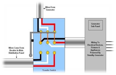
Here’s the 3d part of Nasir’s tutorial on Transfer Switches. If you’re interested in sending articles to the Electrical Engineering Blog, send us a mail! Manuals transfer switches as the name suggests transfers power from one source to another manually. The term manually is important here as there is no solid state automatic transfer of power in this case. It usually consists of a single power cord that runs from the backup generator into the main supply as the alternative source of energy. You simply have to toggle on the switch to backup mode and there you go, power is back. These are mostly used transfer switches for low power and home usage. They usually handle current in the range of 16 to 120 amperes. It can switch even while the generator is running. They are especially handy for portable generators. Operation and Components As far as operation of these switches are concerned they are the simplest. They just consist of a switching panel and powering relays. Circuit breaker may also be used to ensure safety and overloading. As soon as the user pulls down the terminal the switch connections are changed and a relay is energized which in turn powers the switch connected to the backup generator and emergency power continues to flow until switch position are changed again. Availability Options Pre-wired: This is the easiest to install and implement option available. This option provides you with all the necessary wiring you need in a pre-built breaker box. All you need to do is connect wires with it and attach it to your backup generator. It will not only ensure safe use but also provide easy swapping. Inlet box: An inlet box is similar in option to the pre-wired case except that the main wire connecting to the backup generator is housed outside premises of the building to prevent mesh. Outdoor: They provide water proofed housing to allow any seepage in areas that receive heavy rain fall round the year. These switches are usually installed outside house or building to prevent and damage near the main circuit breaker. Types of manual transfer switches Manual transfer switches are not diverse in nature as they are used for domestic and quite simpler purposes. However a brief classification is given below. Simple KITS: These switches are usually used for fast installation and switching in use for residencies and somewhat commercial zones. They consist of switches, power cords and cables. Specified Circuitry: These switches are used for transferring backup power to only intended circuits. Each wire is clearly marked and allows easy and fast installation. They connect only to those load centers which are intended. Rated load centers: They can be used as either main panel or sub panel. They are usually a combination of transfer switches and load centers. They can provide power to 38 to 40 separate circuitries. Single circuit: They are used for providing backup power to single circuits. Only one circuit at a time makes them quite safe and easy to use. They are especially useful for furnaces and pumps and are quite economical as well. Standard switches: these switches are used where current load is from 100-900 A. Like other switches they are fast and efficient but are not economical somewhat. Some precautions Always take into consideration wattage before using any kind of transfer switch. The cord’s ratings should match the generator or main supply ratings. Don’t overload the generator. More the power more the supply. If you have high power generator you can power more circuits at the same time. Always install some monitoring device like some watt mater to be able to know how much power is being consumed and when it exceeds the limits. Always use professional assistance while installing such devices as safety first should be followed strictly.

[via LEKULE]

Follow us @automobileheat – lists / @sectorheat


Operations of Transfer Switch

$
0
0

As we already know that transfer switches are used for switching of load between two distinct power sources as in the case of grid power and backup generator. But the question is how these switches perform this task? What is their operation? The answers to these questions have been answered below. Working principle and operation Due to various types and diverse nature of these transfer switches there operation may vary slightly depending upon the type but overall working is same for all of them. However a brief overview of each type is provided below. Basic Switching The most commonly used transfer switches are made solid state devices. Normally phase relays are used as sensors for sensing voltage drop below a critical value defined as per user requirements. The transfer is automatically initiated as soon as a voltage drop is encountered. A timer is usually used for counting the preset time to de-energize the main control relay and to allow for compensation time for noise that is usually generated when the generator starts. Generator Triggering During this time if at any point grid power is restored to its normal value the timer is reset and the generator is shut down. On the other hand if the main supply voltage doesn’t restore to its full value the timer runs out and generates a starting pulse for the generator to start. As soon as the generator starts another timer (Count after timer) starts its timing. This timer is to allow the voltage and frequency sensing relays to check if the parameters are within the set values for backup power. As soon as the voltage and frequency checking is done the emergency power relay is energized which connects the backup power switch to the main utility circuitry and the backup power starts powering the complete circuit. Re-Transference of Control The same principle is used for re-transference of power back to the grid power. The process initiates when the grid power’s phases reach their preset values. This state is sensed by solid state relays and again the timers and respective relays perform their duty to switch the supply to the main power. Limiting the Voltage A limit switch is also provided in the circuitry to allow the manual change over if needed. The switch is locked at its normal position which is pointing towards the grid power. Lowering the switch manually shifts the power towards backup generator. This limit switch is provided only for emergency and exceptional cases and should be avoided. Automated Switching If you have automated setup available let it do its work unless or until it is out of order or is not performing as you desired. Other types have similar operations like manual switch has no sensing relays and solid state devices. Rather it is a combination of relays and switches and is totally man operated. These switches usually shift the load between small generators and main supply. However solid state switches are heavy duty and are used where large power consumption is occurring and industrial use is intended. Normal use is 16 to 2500 amperes. Uses of transfer switches Transfer switch can be used in various ways. Domestic Use Transfer switches can be used in homes. Low power generators are used in homes or small industries. They are operated through transfer switches. Manual transfer switch is the safest than automatic. Use in circuit breakers These transfer switches are used in circuit breakers to ensure the security of your appliances. The transfer switch protects both generator and utility supply. If the connections or wiring for the generator is not verified, it can cause short circuit to the generator and eventually it can cause the electricity failure or a heavy flame. Till now we have seen the basics of transfer switch along with their operating mode and uses. In the coming part of this tutorial, I will discuss manual transfer switches. It’s a type of transfer switches and as the name suggests it is operated manually.

[via LEKULE]

Follow us @automobileheat – lists / @sectorheat

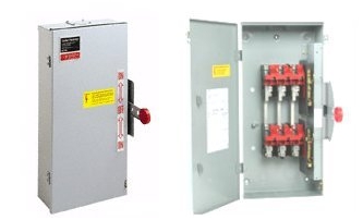
What is a transfer switch?

$
0
0

An electrical device that is used to switch load between two sources is termed as a transfer switch. They are mostly used to connect a generator to one’s household wiring in a safe manner. Nowadays these switches are installed as a permanent part of the control panel and makes switching between the generator and incoming power as simple as operating a bulb switch. It really adds to the safety of household equipment and prevents any dangerous voltage crossing that may lead to fire or any other mishap. Need of transfer switch Transfer switches are usually not used in common houses where there is no need of backup generators. But those having one must use transfer switches to prevent any unwanted situation. Generators are connected to the household appliances via two methods. The first method is to connect generators directly to these appliances using power cord. This method is quite inefficient and looks messy as well creating tangled wires and mesh. This complete situation can be avoided if we connect the generator directly to our household wiring. In this way there would be no need of meshy cords. There would be only one cord which would connect directly to the main circuitry. However this method requires a change over or a transfer switch that may switch the connections as soon as the grid power is turned on. This is really important for the safety of the worker as well as home circuitry. Utility The utility of the switch is just changing the contacts so that the home or any other circuitry may be prevented being powered up at the same time. It involves the switching of contacts from utility to generator power. They perform following functions: Detects if there is any interrupt in the utility power. Nowadays these switches are made using solid state devices and are very efficient in detection of any cut off in the grid power. Sends a signal to the generator as soon as power cut off is detected. This signal instantly turns on the generator and resumes power within Nano seconds. Makes sure that generator is available for power delivery. This point is very important as any lapse in power delivery can lead to data loss or even loss of consumer items. Transfer of load power from utility power to the generator. Detects and generates a signal as soon as the utility power has returned. After the power has returned the transfer switch again shifts the load to the utility power. At the same time it generates a signal that stops the generator. Types of transfer switches There are numerous classes of transfer switches available in market depending upon need. They are classified as following: Open transition transfer switch: These switches are normally referred to as break before make switches. This transfer switch breaks contact with one source of power before contacts are transfers to the generator or backup power source. Closed transition transfer switch: These switches are referred to as make before make transfer switch. As this transfer switch usually makes the new connection before breaking the previous connection so there is some interruption of two incoming powers. Soft Loading transfer switch: A soft loading transfer switch performs active changeover with the incoming power. Static transfer switch: This switch is same as the previous ones except that the changeover is done with help of silicon controlled rectifiers (SCRs) here. Precautions Like every electrical component transfer switches also have some precautions that must be taken into account. All connections must be tight and wiring should be high quality and if possible fire proof. A complete wiring diagram should be made and strictly followed in order to enable easy understanding and troubleshooting in future. That’s all for today. Today, we have seen the basics of transfer switch, its use in daily life and its types. In the coming post, I will explain the internal operation of transfer switch in full detail, so that you guys get an idea of its working.

[via LEKULE]

Follow us @automobileheat – lists / @sectorheat

Switchboards : always more added-value

$
0
0

It is a fact, in the electrical construction sector, a company has no choice but to develop skills to protect its own markets and to avoid falling into a dangerous competitive situation. Meeting with Michel Kajdan, Development Director at Peintamelec  (France). Specialized integrator, Peintamelec makes the assembly and the wiring of electrical panels and switchboards. With 400 employees spread over 7 sites in France and Romania, the group realizes contracts of electrical construction and offers more widely services for industrialization of products, industrial computing, automated handling, integration of energy plants… “We are a company speciliazed in integration, says Michel Kadjan, Development Director at Peintamelec, we have understood a long time ago that making simple switchboards without added value is within the reach of low-cost suppliers. That’s why we decided to  focus on specialized work involving a maximum of technicality.” High added-value Peintamelec realizes for example the integration with high density of electrical components inside electrical panels. The group answers to requests for tenders for electrical installations requiring anti-seismic behaviour, or when there are high thermal or environmental constraints. The engineering department also handles projects with high constraints in terms of electromagnetic compatibility. Not to mention the ability to program some equipments in the workshop. “ Generally speaking, we are willing to answer specifications with high technical constraints! For this, we invest in tools to facilitate the design and the dialogue with the customer. For example, our 3D CAD software gives us the opportunity to present numerical models of wire routing in 3 dimensions. Also, our customers are asking us more and more often to use design tools which are compatible with their own internal digital tools. ” Which choices in terms of devices? “On international contracts, our customers leave us less and less often the choice of the devices to be integrated into the switchboards. It is clear that we are not influencers or specifiers for the standard electrical devices.” Towards a profession more and more specialized Peintamelec has wiremen specialized for some specific markets: “ The more constraints there are , the more technicality  is required, which enables us to protect our business! This profession of electrical installations integrator takes a very “mechanical” turn, especially when dealing with embedded equipments, unlike the traditional electrical distribution for which it is only a question of sheet metal.” The specialization also requires knowing the whole scope of relevant standards . “ By entrusting us with specific achievements , the client transfers to us much of the responsibility for following standards evolutions.” The manufacturing of switchboards and the wiring of devices remains for Peintamelec a very manual job in which each time saving is obviously welcome… “But in this field we do not see significant changes. However, we plan to consider the preparation of wiring upstream of cabling. This may be on this post that we can become more effective , in connection with a change in the way we work …

[via LEKULE]

Follow us @automobileheat – lists / @sectorheat
Warmth, cold, humidity: the proper atmosphere inside the enclosures

$
0
0

Most of the electrical panels and switchboards don’t need any thermal management for their internal atmosphere. The variation range of their internal temperature remains acceptable through the seasons and stays within the limitations imposed by the incorporated devices. However, some electrical switchboards should deal with extremely cold temperatures (technical rooms in the mountain) or with very warm or humid atmospheres (installations in Africa, in the Far East,…). Without going that far, some electrical switchboards contain a high density of power electronics devices. These electronic devices are more and more compact and generate a high level of heat dissipation . It is particularly true as examples for transformers, and for variable speed drives too. This situation is also frequent in little or big computing rooms. So, what are the solutions for electrical switchboards? Fighting against the cold This heating resistance by Legrand is driven by its integrated thermostat or with a hygro-thermostat (right) that enables to manage the humidity level into the enclosure. Source: Legrand Fighting against the cold temperature when switchboards are outdoors or in unheated rooms shouldn’t be the only goal: the condensation risk constitutes a major danger for electronic devices. Corrosion, oxidation, or bad contacts are phenomena that have to be avoided. This condensation is often the result of alternation between warming and cooling (day/night cycle for example). So, there are heating resistances (at a voltage of 12 to 450V AC/DC) controlled by thermostats according to a temperature value and/or by a hygrostat according to a relative humidity point. In large size electrical switchboards, it is recommended to use many low power heating resistances instead of just one high power resistance, in order to obtain an even distribution of the heat along the switchboard. Furthermore, it is usually advised to use heating resistances in addition to heat exchangers or conditioners to avoid condensation. Avoid overheating During the design phase, and when choosing the layout of the devices in the switchboard, it is important to take care of the proper positioning of the more exothermic devices. Their location has a huge impact, to optimize their cooling by natural convection (natural displacement of the air masses inside the enclosure), and to prevent that the heat they dissipate may provoke the overheating of the other devices, in particular the most sensitive ones. If, despite that, the heating risk stays too high, it is necessary to consider complementary measures to lower the temperature. A number of solutions are available: – First approach: Would a simple fan be enough to evacuate the excess of heat dissipated ? Using fan and filters is an extremely cost-effective method to evacuate large quantities of heat dissipated out of the electrical switchboard. Anyway, they can only be used under two necessary conditions: the switchboard’s external ambient atmosphere must not be too polluted and the external temperature has to remain much lower than the switchboard’s internal temperature. Last thing, the fan and filter unit must integrate an EMC protection when the devices inside the switchboard require EMC protection. – When the air, out of the switchboard, is too polluted to use fans , the air/air exchanger enables a thermal exchange without contact between flows. This means that the external dust cannot enter inside the switchboard. However, the difference between the external and the internal switchboard’s temperature impacts directly the quantity of heat dissipated that can be evacuated. The calorific power of that kind of system is defined in W/°C. – When the external temperature stays too high to enable a simple thermal exchange , then it becomes necessary to use a cooling unit or an available refrigerating source. Hence a solution with an air/water thermal exchanger has to be used along with a central cooling unit or a cooling water circuit. This solution, quite heavy, is generally only considered for a minimum number of switchboards to cool down. -More autonomous is the enclosure cooling unit (enclosure air conditioner) which makes it possible to cool individually the atmosphere of every enclosures’ closed compartments. This thermodynamics solution offers a pretty high efficiency level. With 4 levels of power, 3 kinds of supply voltages and different casings adapted for electrical enclosures, Schneider Electric offers a range of 66 models of enclosures’ air conditioners from 1.1 to 2.7kW. Source: Schneider Electric Switchboard manufacturers integrate these enclosure cooling units inside or outside the switchboards enclosure (in the thickness of the door, on the side or even on top the enclosure). A connection to a door switch enables to stop it when the door is opened, and a restarting with a timer. Condensation water is automatically evacuated. -There are finally some clever solutions which enable to evacuate the heat dissipated at its source . As such, some enclosure manufacturers offer to install variable speed drives through the back of the enclosure, so that the VSD radiator evacuates the calories directly outside of the switchboard. Direct cooling at the heat dissipation source is a developing trend. Rittal offers a “cold” mounting plate, cooled by a liquid circulation. Source: Rittal Adding a fan on this external radiator improves the efficiency of this configuration. Other solution: to install, at the source of the heat dissipation, a special mounting plate cooled by a serpentine integrated at its rear face, with cold water provided by an external source. For the most exothermic devices, the trend is to control the heat dissipation at its source. Think also about the computer servers’ domain, where manufacturers go up to the direct cooling of the microprocessors with a liquid exchanger!

[via LEKULE]

Follow us @automobileheat – lists / @sectorheat

Training courses for panel builders: what, where?

$
0
0

I don’t !! Read below the point of view and experience of Denis LAUDREN, who has been involved in panel building for many years, and who develops and animates today some training courses dedicated to panel builders. DAN ____________________________________________________________________________________ DAN :  ” so Denis LAUDREN, please tell us about your experience around training for panel builders ” Denis LAUDREN: ” I’ve been working around panel building activity for more than 20 years, as manager of this type of activity, or as creator and animator of training sessions recently. It is a very exciting job, but also very complex and generating some risks. Every customer is specific, and every request is different. Each project is for us a kind of adventure, a specific case. P anel building activity is also rich and exciting due to the diversity of knowledge & competences it is necessary to master if you want to be « efficient » , and thus profitable: – Understand properly what the customer needs – Prepare a technical & commercial offer in line with customer needs – Negotiate the contract terms – Design & build projects in line with customer requirements and with your objectives (margin …) Furthermore, competences and knowledge required are constantly evolving : – Design offices are more and more losing their expertise to advise on LV system / switchboard design, so panel builders (and/or contractors) have to help the end users or design offices to define their switchboards. – New customer values are emerging (like energy efficiency …), panel builders should be able to push and propose solutions to match these expectations. Adaptation of panel builders to this world in permanent mutation can only be done through regular and pro-active training of the people to be sure they have the right skills to match the new challenges. But who should be trained? And on which subjects? Though training is probably the most profitable investment a company can do, you cannot afford to spend all the time of your resources on training, as daily business tasks need to be done. So, in order to establish a well balanced training program, it’s better to first do what I call a “quality diagnostic” of your company . It will highlight your strong points, and also the ones where improvement could be done . I developed such a “diagnostic tool”, in 2007, which I use at the beginning of a training I developed at that time for Schneider Electric: it makes it possible for each participant to visualise where they are today and what are their main improvement routes. This tool is looking at the different competence areas of a panel builder: – Quality system – Organisation – Request for tender / customer relationship – Technical and commercial offer – order registration – Technical studies / design – Manufacturing – Quality inspection – Project management This type of diagnosis is obviously one of the possible sources for you to define your training plan priorities. At the same time, to my experience, existing training offers dedicated to panel building skills & activities are very “rare” on the market : the ”traditional” educational system , in most countries, is pretty well adapted to prepare on technical competencies needed for the job (electro-technical knowledge, assembly, wiring …), but does not prepare properly skilled people on 2 essential required competences : – Management of tendering, to win orders – Management of projects, to ensure customer satisfaction and profitability In France, several training institutes , like Cegos and Demos, propose training modules dedicated to this type of needs : though they are not specifically targeted at panel building activity, they can be, from my experience in animating such sessions, a perfect basis to train your people on project management skills. More specific training modules , dedicated to panel builders, have sometimes been developed by specialized training companies such as mine, or sometimes by large manufacturers (like the ones I developed for Schneider Electric) wanting to help their panel builder “partners” to be the best on the market. Without training , whether you organise it with your internal resources or with the help of external people, your company has little chances to improve its efficiency and thus survive in a more and more demanding and competitive world . My suggestion, to conclude : is that you should take the time to formalize your ambition (where I want to be tomorrow?), to evaluate your existing competences, and from that point to build your training plan for the coming years. The solutions exist; it’s up to you to decide how to use them for your best benefit. ”

[via LEKULE]

Follow us @automobileheat – lists / @sectorheat
Viewing all 1695 articles
Browse latest View live